NPN vs PNP, dry contacts and safety relays explained
NPN vs PNP sensor outputs, light-on and dark-on, dry contacts, and why a standard relay can't do a safety relay's job. A plain wiring guide for plant engineers.
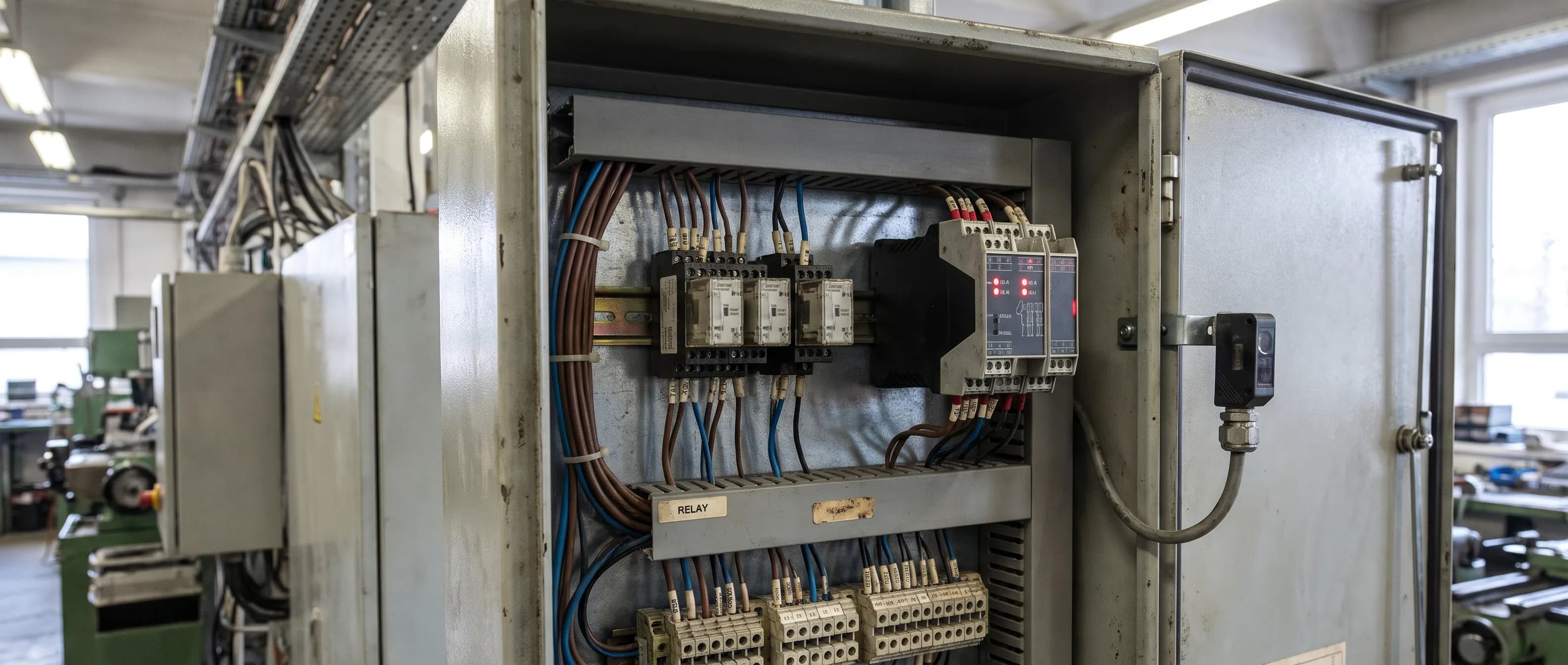
A new photoelectric sensor arrives for a conveyor. The PLC input never changes state. The sensor LED blinks happily, the wiring looks right, and someone suggests swapping the sensor. Often the sensor is fine. The real question was NPN vs PNP, and nobody checked the input card.
This guide covers the wiring questions that come up when a sensor meets a controller: sinking vs sourcing, light-on and dark-on, relay vs transistor outputs, dry contacts, and the one that matters most for people, the difference between a standard relay and a safety relay. At the end we show where an AI camera's output fits, and where it does not.
NPN vs PNP: what's the difference?
A PNP (sourcing) output switches positive voltage to the load when it turns on. An NPN (sinking) output connects the load to the negative supply, usually 0 V. As Machine Design's piece on sensor outputs explains, the names come from the type of transistor that drives the output.
The sensor does not decide which one you need. The input does. A PLC input card is built as sinking or sourcing, and a sensor output that doesn't match it will simply never be read. Machine Design also notes that some multi-mode sensors detect the connected load and behave as NPN or PNP on their own.
A quick checklist before wiring:
- Read the input card manual: sinking or sourcing?
- Confirm the sensor output type from the part number, not the box label.
- Write the supply voltage (usually 24 V DC) and the common (0 V or +24 V) on the drawing.
- Wire to the sensor manual's diagram, then test every state one by one.
Sinking vs sourcing in practice
The naming confuses people because it describes the output, not the input. A sourcing (PNP) sensor needs a sinking input, one that takes current in and returns it to 0 V. A sinking (NPN) sensor needs a sourcing input. If a plant runs machines from different builders, expect both types. The drawing for each machine is the only reliable answer.
Light-on, dark-on, NO and NC
In light-on mode, the output turns on when the receiver sees its own light. In dark-on mode, it turns on when it does not. Machine Design maps light-on to a normally open (NO) output and dark-on to a normally closed (NC) output, giving four combinations: NO-NPN, NO-PNP, NC-NPN and NC-PNP.
The practical rule: ask "do I want a signal when the object is there, or when it is gone?" and answer it together with the sensor type. In a through-beam sensor the object breaks the beam, so "object present" means "light lost." In a diffuse sensor the object reflects light back, so it is the other way round.
Wire breaks follow the same logic. A broken cable means "no signal." A design that reports a dangerous state with "signal on" will report nothing at all when the cable is cut. That idea sits at the heart of how safety circuits are built, and it is why they fail to a stop.
Relay vs transistor output
A relay output is a mechanical contact. Because the contact is isolated from the sensor's own circuit, it can switch a load at a different voltage. A transistor output has no moving parts. Hokuyo's glossary of output types notes that transistor outputs respond faster, have no wear-out life tied to the number of operations, and can drive DC loads only.
Relay contacts wear a little with every switching cycle and respond more slowly. That is why a high-speed counting conveyor sends a transistor output straight into the PLC. A relay output makes sense when the load switches rarely and runs at a different voltage. For response time and contact life, use the datasheet of the exact model; the numbers vary widely.
What is a dry contact?
A dry contact (potential-free contact) is a switch contact with no voltage of its own. It only opens and closes. The circuit it is wired into supplies the voltage.
Its strength is compatibility. The same dry contact can feed a PLC's 24 V DC input, a siren circuit, or the "open" input of a door controller. Its limit is the contact rating. Loads above the rated current or voltage go through an interposing relay or contactor.
Safety relay vs standard relay
A standard relay just switches. If its contact welds or sticks, nothing notices, and the machine may keep running. A safety relay is designed so that a single component failure still brings the machine to a safe state, and the fault is caught before the next start.
ABB's safety relay section opens with the requirement in heading 1.2.1 of the EU Machinery Directive 2006/42/EC: a fault in the hardware or software of the control system must not lead to a hazardous situation. The same document lists what a safety relay adds:
- Redundancy: two separate circuits control the outputs. If one fails, the other stops the machine. ABB compares this to the dual brake circuits in a car.
- Checked every cycle: the redundant circuits are checked at each operation, and the machine can only start if both are healthy.
- Input monitoring: inputs are checked for short circuits, and the safety devices and their cables are monitored.
- Supervised reset: the reset button must be pressed and released. ABB notes that many serious accidents have been caused by an unintentional, unsupervised reset.
Force-guided contacts make that monitoring possible. As Machinery Safety 101 explains, relays covered by IEC 61810-3 have contacts that are mechanically linked. If one contact welds, the mechanism locks, so the state of the NC contact tells you the state of the NO contact.
One caution matters more than the rest. ABB states that its relays are internally built to the highest level (Category 4 under EN ISO 13849-1). In the same document it stresses that this category describes only the relay configuration, and that input devices, output devices and wiring must all be considered for the category of the system. Fitting a safety relay is not the same as validating a safety function. Our machine guarding guide covers the wider picture, including OSHA's guarding rules for US plants.
NPN vs PNP, relay or safety relay: which goes where?
| Property | Relay-output sensor / interposing relay | Transistor (NPN/PNP) output | Dry contact | Safety relay |
|---|---|---|---|---|
| Typical use | Infrequent switching, different-voltage load | PLC input, high-speed counting | Signal between independent systems | E-stop, interlocked guard, light curtain |
| Speed | Limited by the contact, slower | Faster | Depends on the device behind it | Per manufacturer data |
| Load type | AC or DC, within contact rating | DC only | Within contact rating | Safety circuit |
| Fault monitoring | None | None | None | Yes (redundancy, checked every cycle) |
| Suitable for a safety function? | No | No | No | Yes, if the whole system is validated |
Where does an AI camera's output fit?
An AI camera such as ISEE-CAM provides dry-contact outputs. In the table above it sits in the "dry contact" column, not the safety relay column. The camera is not a safety relay or a safety circuit, and no PL or SIL rating is claimed for it.
The ISEE-CAM PLC integration page describes the wiring: three outputs (PLC triggering, alarm/beacon, machine stop) and one trigger input from an external system. The outputs are dry contacts wired to PLC inputs or safety relays. Event and status data go to the PLC and SCADA layer over OPC-UA, Modbus TCP and REST API.
The same page is clear about the relationship. The camera's PLC output works with the machine's safety system and does not replace it. Certified light curtains, safety laser scanners and safety PLCs keep the safety function. Detection runs on the device, and alert-to-output latency is under 100 ms, but the machine's own stopping time still applies after the signal, so zone sizes are planned with it in mind.
In practice the outputs are used to:
- Send a stop request to the PLC when a person is detected in a hazardous machine area.
- Drive a siren, beacon or warning light directly.
- Tell a door controller to open when a forklift or a person arrives, as described in our industrial door photo eye guide.
What the camera adds is area coverage and classification. It watches a whole zone instead of one beam line, and it can tell a hand from material, or a forklift from a person. That is an awareness layer next to the light curtain, interlock or e-stop circuit wired to the safety relay. We compare the two directly in light curtain or AI camera, and discuss when an alert should become a machine action in AI safety camera alerts.
FAQ
What is the difference between NPN and PNP?
A PNP output switches positive voltage to the load; an NPN output switches the load to 0 V. Choose the one your PLC input card or control circuit expects. A mismatch means the signal is never read.
Can I connect a PNP sensor to an NPN input?
Not directly. You need a sensor that matches the input, a multi-mode sensor, or an interposing relay whose coil is driven by the sensor and whose dry contact feeds the input.
What is a dry contact?
A contact with no voltage of its own that only opens and closes. The connected circuit supplies the voltage, which makes it easy to wire between independent systems.
Can a standard relay replace a safety relay?
No. A standard relay cannot detect a welded contact or a cable fault. A safety relay catches these through redundancy, cycle-by-cycle checks and supervised reset. The safety level is set by the whole circuit, not the relay alone.
Conclusion: three questions before you wire
NPN vs PNP is the first question, not the only one. Before wiring any sensor, settle three things: the output type (NPN, PNP or relay), when the signal should be on (NO or NC), and how fast the load has to switch.
Where people are at risk, the line is clear. The protective function runs through a safety relay or safety PLC in a circuit validated as a whole. An AI camera's dry-contact output adds information and warning to that circuit. It is not the circuit.
Want to see how ISEE-CAM would wire into your existing PLC and safety circuit? Tell us about your panel and the scenario you want to cover, and we will propose the zones, outputs and wiring. Contact our engineering team.
Contact: info@isee-vision.com · +90 216 455 95 44